

Photo: Master Corporal Alana Morin, Joint Task Force — North, Yellowknife
The northern lights over Inuvik, Northwest Territories during Operation NANOOK-NUNALIVUT on February 28, 2025.
Alexander Michael Daniel is a Defence Scientist and operational researcher with the Center for Operational Research and Analysis (CORA) at Defence Research and Development Canada (DRDC). He completed a Master’s degree in electrical and computer engineering at the University of Toronto in 2017, and joined DRDC’s Ottawa Research Centre that same year, where his research focused on radar signal processing and resource management. Since moving to CORA in 2019, his work has included both machine learning applications to open-source intelligence and operational research in support of NORAD modernization. He is currently a member of CORA’s NORAD Operational Research Team at Peterson Space Force Base in Colorado Springs.
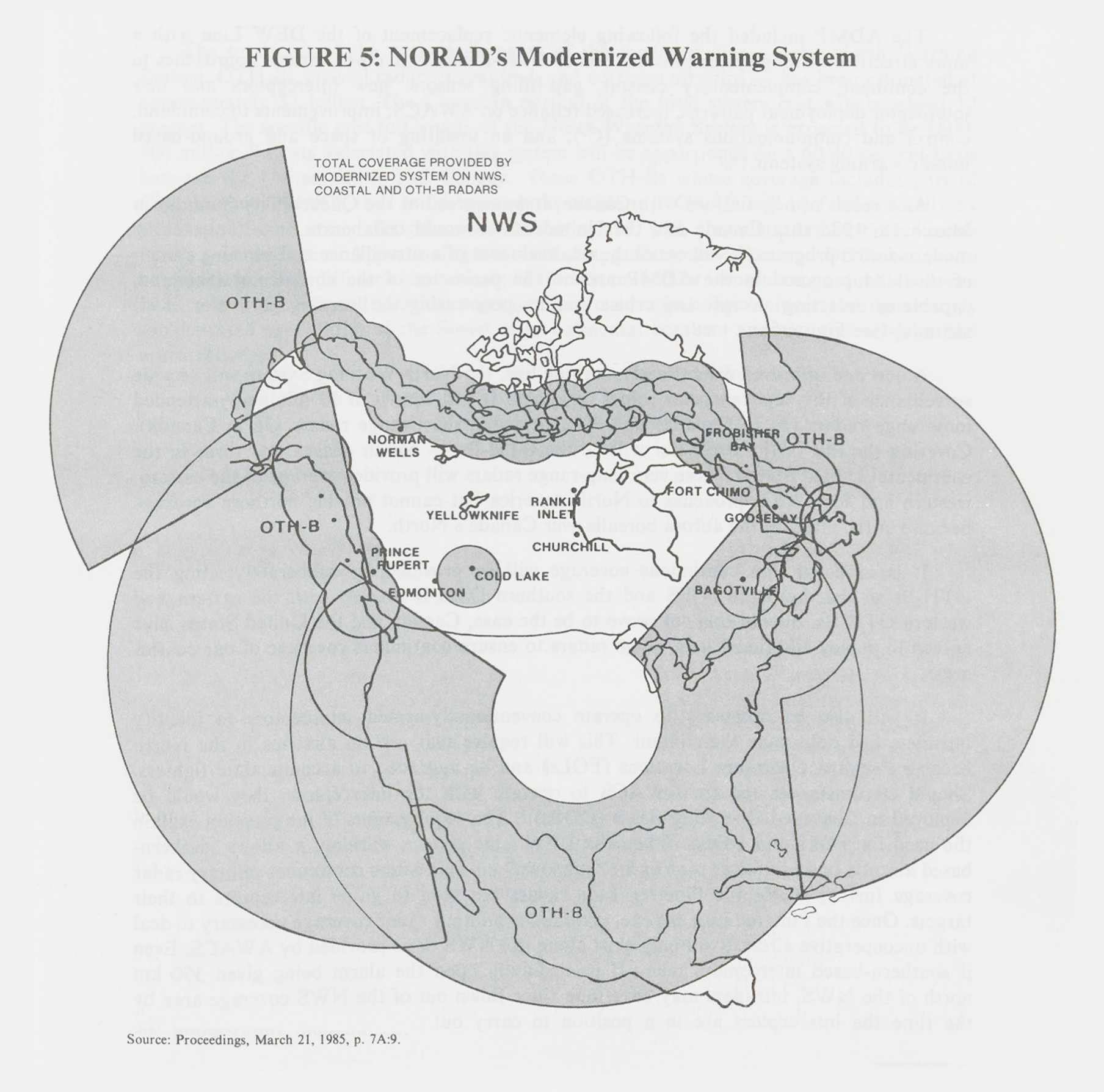
On 20 June 2022, when Canadian Minister of National Defence (MND) Anita Anand announced the plan to create a “Northern Approaches Surveillance system” as part of the Canadian government’s approach to modernizing the North American Aerospace Defence Command (NORAD), three initiatives were identified as the “backbone” of the new system.Footnote1 Given that two of these, the “Arctic” over-the-horizon radar (OTHR) and the “Polar” OTHR, were to be used to monitor the northernmost reaches of the continent, one could forgive students of history for being skeptical of the announcement: NORAD has tried-and failed-to use OTHR in the Arctic before. A 1967 plan to replace the Distant Early Warning (DEW) Line of radars in the north relied heavily on the use of cheaper OTHR technology.Footnote2 While there was already some scepticism about the viability of north-facing OTHR at the time of the plan’s release, by the mid-70s, whatever “original optimism” there had been was “diminished substantially.”Footnote3 A decade passed with little to show for it, and the eventual 1985 plan to replace the DEW Line was to make use of OTHR to look in every direction but north; see Figure 1.Footnote4 Indeed, in their recent (and excellent) book, NORAD experts Andrea Charron and James Fergusson dedicate only a single doubtful sentence to the prospect of using OTHR to replace the aging North Warning System (NWS): “…over-the-horizon radars may provide a solution (assuming the problem posed by atmospheric variations at high altitudes can be solved)…”.Footnote5
Was the MND wrong to entrust our northern flank to a technology with this track record? This article will show why the answer to this question is no. An overview of the history of OTHR in North America is given, interspersed with technical “interludes” which, taken together, illustrate how OTHR works in general, why it failed in previous attempts to use it for Arctic surveillance, and how recent innovations have made it a viable choice for a modernized NORAD.
Figure 1: A map of North America showing the radar coverage of the 1985 plan to modernize NORAD’s surveillance system. OTHRs are used for surveillance in all directions but north, where the NorthWarning System’s ground-based radars are used.
A Brief History of OTHR Development In North America
In the Second World War, radar had, in the words of one author, “altered the basis of warfare more profoundly than any of the inventions that had marked the industrialization of combat.”Footnote6 After the war, radar research continued commensurately.Footnote7 Groups in several countries had interest in the development of High Frequency (HF) radar as, in that band (3-30 MHz), waves had unique modes of propagation that could enable detection of targets beyond the radar’s usual line-of-sight horizon.Footnote8 By 1956, the Naval Research Laboratory (NRL) had successfully completed “definitive” experiments showing an HF radar could send a wave through the earth’s ionosphere to illuminate an aircraft located beyond the horizon and, subsequently, detect the echoes of that illumination with a receiver.Footnote9 In other words, they demonstrated the possibility of an “over-the-horizon” radar.
Motivated by this success and the contemporaneous advances of signal processing techniques, NRL began the development immediately thereafter of the “Magnetic Drum Radar Equipment” (MADRE) in Chesapeake Bay. Full operation of MADRE began in the fall of 1961, and NRL was soon able to detect and track commercial passenger flights over the Atlantic Ocean; the “program’s primary goal of an order of magnitude increase in range for aircraft detection and track was achieved.”Footnote10 A separate effort at Stanford in the early 60s developed the “Wide Aperture Research Facility” (WARF), with two sites in California. The WARF improved upon MADRE by providing better spatial resolution in its measurements and ultimately influenced the design of subsequent OTHR systems in both the U.S. and Australia.Footnote11
By the turn of the century, the U.S. had fielded several operational OTHR systems. These include the AN/FPS-95 (code-named “Cobra Mist”), which was built in the late 60s in collaboration with the U.K. on the east coast of England for the purpose of monitoring “air and missile activities” in the Soviet Union. After scientific tests started in mid-1971 uncovered unresolvable technical errors, the program was ultimately terminated in the summer of 1973, and the radar was dismantled and removed from the test site.Footnote12 The AN/FPS-118 was developed in the late 70s and was included in the 1985 plan to modernize NORAD’s warning architecture; see the OTH-B (“B” for “backscatter”)Footnote13 radars in Figure 1 and further discussion below. Though two of these radars were built (one each on the east and west coasts of the U.S.), the program was ultimately stopped after the Cold War ended as there was no longer a perceived need for them.Footnote14 Finally, the AN/TPS-71 “Relocatable” OTHR (or “ROTHR”)—so named because it could be packaged up in one location and transported/rebuilt at another—was developed in the mid-80s. Originally motivated by the threat of bombers in the air and missile carriers at sea, the ROTHRs, located in Virginia, Texas, and Puerto Rico (and facing south) are now used primarily for drug interdiction.Footnote15 Indeed, the systems are still in use today: in 2021, Raytheon won a five-year contract to operate and maintain the ROTHR systems, which reportedly “contributed to the seizure of 26 metric tons of cocaine from drug smugglers attempting to cross into U.S. territory” in 2020.Footnote16 Results like these make it easy to understand the claim, in the words of NRL scientist Joseph Thomason, that OTHR is “one of the more significant radar developments since World War II.”Footnote17
Technical Interlude 1 – How Does OTHR Work?
Though the details become quite involved, there are two basic principles common to all OTHRs that are necessary to understand now to make sense later of the “aurora challenge”. The first principle is that of refraction, the way electromagnetic waves change direction at the interface between two different media in which the wave propagates. Refraction is caused by changes of the speed of the wave as it enters the new medium and is what causes rainbows and the appearance of a straw bending when submerged in a glass of water (Figure 2).Footnote18 Figure 3 illustrates the concepts relevant to this article. First, when a wave travels from a slower medium to a faster one, the wave bends towards the boundary. Second, as the incident wave approaches the boundary, it reaches a point where the refracted wave becomes parallel to the boundary—this angle at which this occurs is known as the critical angle. Third, when the incident ray is even closer to the boundary, there is no refraction at all. The ray simply reflects back into the slower medium, a phenomenon known as total internal reflection.Footnote19
Figure 2: A straw in a glass of water. Refraction of light causes the straw to appear bent and disjoint in the water.

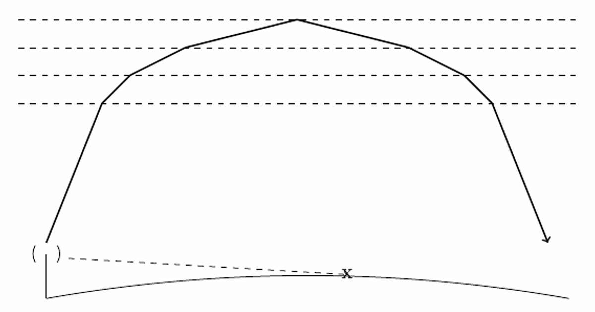
Some electromagnetic waves emitted by the sun have such high energy that, when they impinge upon the earth’s atmosphere, they ionize the gas they encounter, i.e., they create electrically-charged particles. This atmospheric layer of ionized gas (technically, a plasma), which ranges from roughly 50 to 1,000 km above the ground, is known as the ionosphere. The heavy presence of charged particles in the ionosphere differentiate it sufficiently from the neutral atmosphere we experience at ground level to enable refraction both at and within the ionosphere.Footnote20 Figure 4 provides an exaggeratedFootnote21 illustration of how OTHRs can use ionospheric refraction to send waves through the ionosphere and back towards the earth. As the wave enters this toy model ionosphere of discrete layers, it undergoes refraction towards the boundary at each layer. When the angle is so great that a total internal reflection occurs, the wave back is sent down to the earth (where it undergoes refraction several times again). This is the skywave propagation that enables the radar to detect targets that go beyond the line-of-sight horizon.
Figure 3: Illustrating refraction (solid blue line), the critical angle (red dotted line), and total internal reflection (magenta dashed line), for an electromagnetic wave traveling from a slower medium to a faster one.
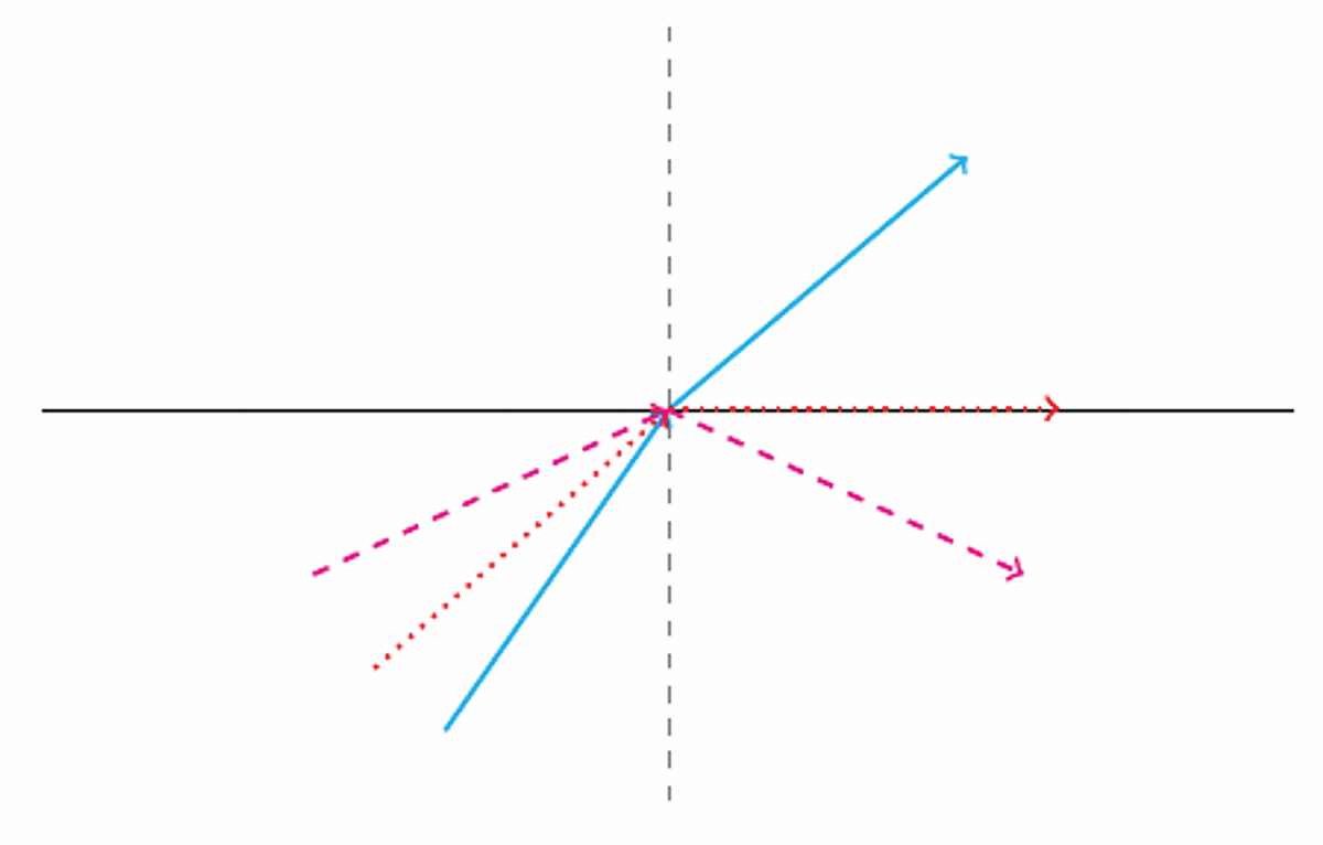
Figure 4: Illustrating skywave propagation via refraction through a toy ionosphere of distinct, homogeneous layers. The skywave is able to see far beyond the line-of-sight horizon of the radar.
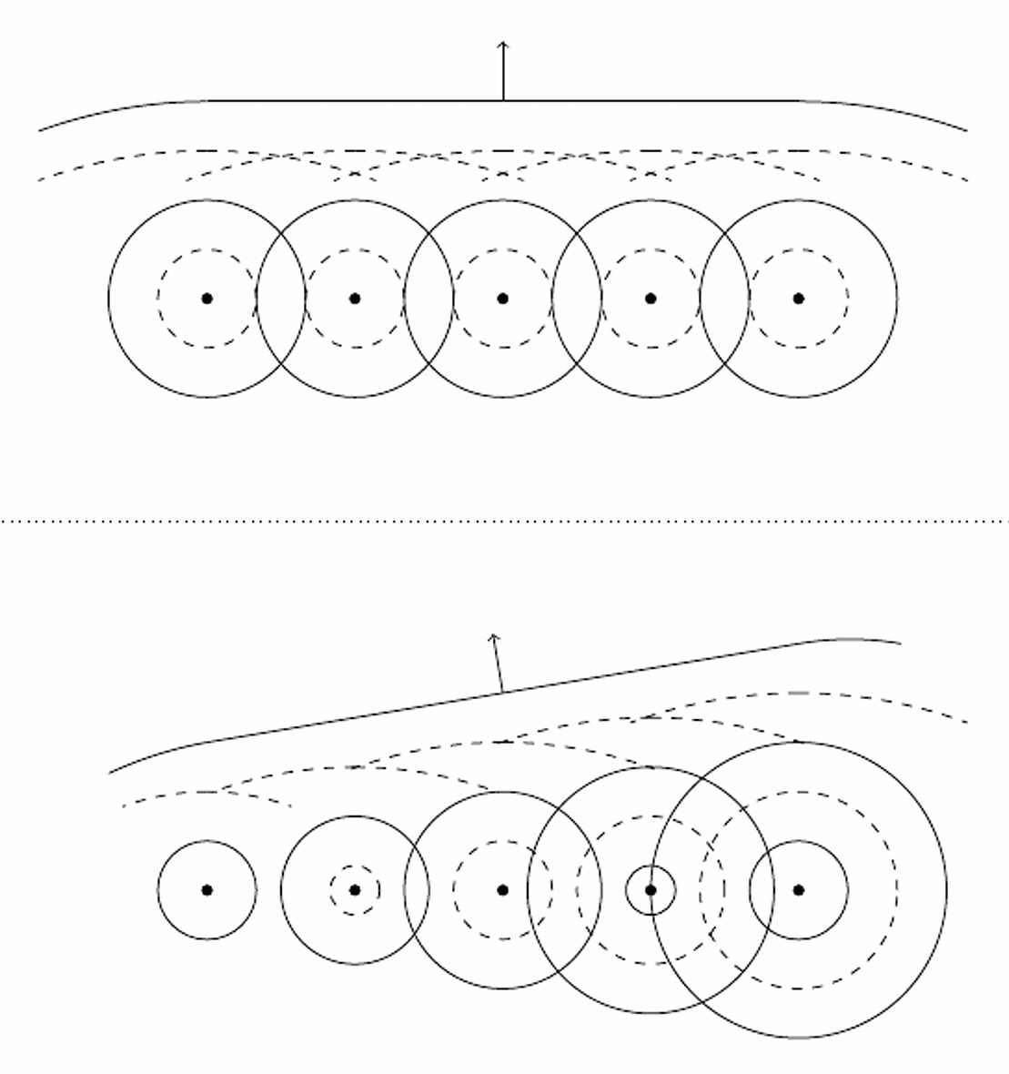
The second important concept is the beamforming of antenna arrays. The analogy here is to pebbles in a pond. A single pebble, when dropped in water, produces circular ripples emanating outward from the pebble. When multiple pebbles are dropped, however, the waves they produce undergo constructive and destructive interference, producing patterns far more complicated than any single pebble could produce. Antennas, like pebbles, produce waves with distinctive spatial patterns. When the outputs of many antennas are combined carefully, they too can produce cumulative patterns unlike anything a single antenna could do individually. Figure 5 provides an exaggerated illustration of a linear array of antennas (or pebbles) that individually produce waves uniformly in every direction. When all antennas are activated in lockstep, the net interference (at distances far from the array) is well approximated by a single wave propagating normal to the array; however, when the antennas emit waves with a slight offset, the direction of the cumulative wave is no longer normal to the array. Controlling the offset thereby controls the direction of the transmitted wave. Analogous processing can be done with a receiving array, enabling the radar to, for instance, substantially diminish returns (like interference or deliberate jamming) from certain directions.Footnote22
Figure 5: Illustrating how the combination of outputs from individual antennas can yield plane waves in different directions.
The skywave propagation can enable systems to detect targets as far out as 4,000 km, while operational systems have historically had antenna arrays capable of sending waves at angles as large as 30 to 45 degrees to the left and right of normal.Footnote23 A single OTHR can thus be capable of covering millions of square kilometers, leading NRL scientists James Headrick and Joseph Thomason to describe it as “the most economical sensor on a dollar per square mile basis, where its products and reliability satisfy the mission.”Footnote24
The Failure of OTHR in the North
Headrick and Thomason are not the only ones to have appreciated the possible cost savings of OTHR. Although the Distant Early Warning (DEW) Line of radars was completed only in 1957, continental defence planners considered replacing it with OTHR (among other things) as soon thereafter as 1967.Footnote25 The DEW Line was expensive to operate, and, consisting as it did of ground-based radars in the far north, provided a series of easy targets for adversaries, providing only a limited line-of-sight ability to detect them. On all three fronts, OTHR seemed like it would be an improvement.Footnote26 Indeed, the plan estimated that the existing system cost $903 million USD a year to operate, while the proposed replacement system, OTHR included, would only require $342 million a year.Footnote27
The 1967 plan included a provision approving “a programmed force of two [OTHR] sites beginning in” the 1973 fiscal year.Footnote28 By 1972, this plan was significantly revised, the 1973 target would not be met, to 4 OTHRs, each with 180 degree coverage, with initial operational capability (IOC) by 1977-78.Footnote29 When the difficulties in dealing with the auroral clutter problems for north-facing OTHR are appreciated, see Technical Interlude 2 below, this delay is easy to understand. The experimental “Polar Fox II” OTHR was built in the summer of 1971 in Caribou, Maine, and used in north-facing OTHR experiments in 1971 and 1972.Footnote30 The report for one of the experiments aptly summed up the difficulties: “Under unfavorable conditions, which in Arctic regions north of 60° geomagnetic latitude occur fairly often, a backscatter radar may see the ground only in very limited range sections.”Footnote31 The subsequent “Polar Cap III” tests began in December of 1972, with a transmitter and receiver in Hall Beach and a second receiver in Cambridge Bay (now both in Nunavut). The “poor results” over 24 months meant that by 1975, “planners concluded that for the present the aurora challenge could not be overcome, and directed that studies of alternative approaches be undertaken.”Footnote32
These results required a reversal of a 1973 decision to close the DEW Line (and replace it with OTHR) by 1976. Indeed, such was the outlook on OTHR at the time that in 1976, U.S. Secretary of Defense Harold Brown nearly cancelled the program altogether, despite himself being responsible for the 1967 plan that first brought up the possibility using OTHR for northern surveillance. Though the OTHR program ultimately survived, Brown had no choice but to approve the new Project “Seek Frost” in 1977, which planned to replace the now twenty-year-old DEW Line with modernized ground-based radars.Footnote33 When an agreement to modernize the DEW Line was ultimately finalized in 1985,Footnote34 OTHRs (specifically AN/FPS-118 or “OTH-B” radars) were to be used for surveillance in every direction but north (Figure 1): the aurora challenge could not be overcome.
Technical Interlude 2 – The Aurora Challenge
Consider a person driving in the direction of the sun at sunset (Figure 6). The sun is low enough in the sky that it appears in his field of vision, and due to the intensity of the direct sunlight, it dominates the light that is reflected off the road and any vehicles in front of him.
Figure 6: Direct sunlight interfering with vision of the road. Illustration provided by Sarah Tierney, DRDC Science Visual Documentation Team.

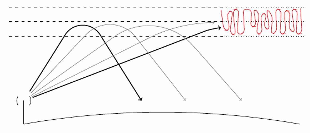
An analogous problem occurs with north-facing OTHR (though as we shall see, rather than it being due to an external source of interference, it something of a self-inflicted wound). Complex interactions between the ionosphere, the Earth’s magnetic field, and solar winds produce high-speed irregularities in the ionospheric plasma that “reflect radio waves very efficiently.”Footnote35 Figure 7 illustrates how this is becomes a problem for north-facing OTHR. An OTHR based on a linear antenna array (discussed in the previous Technical Interlude) requires a broad beam to ensure “target illumination at all possible elevation angles.”Footnote36 Figure 7 shows how, while some portions of this broad beam refract through the ionosphere back towards the earth, other portions illuminate the auroral plasma irregularities. The two thick black lines in Figure 7 have approximately the same length, so any targets illuminated by the upper black ray will appear at approximately the same distance as the irregularities illuminated by the lower black ray: range cannot therefore be used to distinguish targets from clutter.Footnote37 A back-of-the-envelope calculation can be used to show that the auroral clutter returns can be orders of magnitude more powerful than the returns of intended targets;Footnote38 indeed, they can “incapacitate” an OTHR.Footnote39
Figure 7: The broad beam of an OTHR can illuminate the ionospheric irregularities (red squiggle).
Note that not merely the presence of clutter is difficult to deal with. OTHRs at all latitudes must deal with clutter from the Earth’s surface, which will also reflect the radar’s emissions back towards it. What makes OTHR feasible is the fact that these returns are generally “well-confined in spectral content to the very low Doppler frequencies.”Footnote40 In simpler terms, the Earth’s surface and things on it move at relatively low speeds, so high-speed targets like aircraft can be distinguished from the low-speed surface clutter by considering the speed of the targets detected, i.e. the Doppler shift of the returned waves.Footnote41 In contrast, the plasma irregularities causing auroral clutter can move fast enough to mask high-speed aircraft, so differentiating auroral clutter from targets using the Doppler shift is not in general possible.Footnote42 This, therefore, is the aurora challenge: north-facing OTHRs cannot distinguish auroral clutter from legitimate targets of interest either in range or in speed, the two most basic means by which radars in general detect their targets.
OTHR in the New Millennium
Again we turn to NRL’s Joseph Thomason, who, writing in 2003, describes the state-of-the-art in OTHR at the time: “All operational HF sky wave radars [i.e., OTHR] designs rely heavily on 1970’s thinking and technology.”Footnote43 Could the new millennium provide new opportunities and approaches to OTHR in the north?
Since 2006, researchers at Defence Research and Development Canada (DRDC), led by Dr. Ryan Riddolls, have been exploring precisely this possibility: “it was the realization that next-generation OTHR techniques being proposed for midlatitude systems, such as planar antenna arrays and multiple-input multiple-output methods, could be applied to attack the unique problems of high-latitude OTHR”Footnote44 [references in original omitted], see Technical Interlude 3 below. In addition to extensive mathematical modelling, experimental results have been obtained and analyzed using experimental OTHR systems, including a 256-element antenna array in Ottawa and a 1024-element array in Nunavut.Footnote45 This distinguishes the current period of NORAD modernization from the 1967 plan: the latter proceeded in the hopes that north-facing OTHR might eventually be figured out, while the former is occurring only after more than 15 years of study and development on that very problem.
Technical Interlude 3 — Overcoming the Aurora Challenge
Consider again the driver from Figure 6. The sun is overwhelming his eyes, limiting his ability to see the road and vehicles in front of him. Alas, the driver’s sensors (i.e., his eyeballs) do not allow him to “turn down” the sun or “turn up” the road. Wearing sunglasses reduces the intensity of the sun’s rays but does not improve the contrast between the sun and the road. Nevertheless, one feature of this interference can be exploited to mitigate it: elevation. Broadly speaking, the sun is in the uppermost portion of the driver’s vision, while the road is only in the lower portions. Lowering the car’s sun visor blocks the sun’s incident rays, allowing the driver to see the road again (Figure 8).
Figure 8: Spatial processing to null a mainbeam jammer, or in other words, blocking the sun with a sun visor. Illustration provided by Sarah Tierney, DRDC Science Visual Documentation Team.

An analogous idea can be exploited in modern OTHR systems. Recall the illustration of plasma irregularity illumination in Figure 7. Although the part of the beam illuminates the plasma, it is only the lower portion of the beam that does so. Even though auroral clutter occurs at the same ranges and speeds as legitimate targets, the elevation angle provides a means of distinguishing the two, just as the difference in elevation of the sun and road enables Archie to block out one but not the other.Footnote46
This concept requires the antenna array to be able to distinguish between different elevation angles. Linear antenna arrays, as illustrated in the first Technical Interlude and used in all of the older OTHRs discussed in this article, permit distinction only in azimuth. Adding a second dimension to the antenna array, i.e., using a planar array, adds a second dimension in angular control, namely elevation. The two test arrays discussed in the previous section are not just (respectively) 256 and 1024 element arrays, they are 16-by-16 and 32-by-32 square arrays.Footnote47
The use of a planar array enables, in principle, two possibilities. First, when transmitting using a planar array, the transmit beam can be steered in elevation (as beam steering in azimuth was depicted in Figure 5) to avoid generating the clutter in the first place. Second, when receiving using a planar array, signal processing techniques can be used to mitigate the input from certain directions as discussed in the first Technical Interlude; this is a closer analogue to the driver and the sun visor. Thus, directions containing auroral clutter can be suppressed, while directions that targets are expected to be in can be (comparatively) amplified.
Conclusion
Despite a history of difficulty in getting OTHR to work for Arctic surveillance, the government has not made a mistake in planning on OTHR forming the “backbone” of the future Northern Approaches Surveillance System. The OTHRs that were built and used beginning in the 60s were linear arrays which could distinguish targets of interest from (nearly) stationary ground clutter, but not from auroral clutter which masked targets in range and speed; this is the “aurora challenge” that made all attempts in the last third of the 20th century to use OTHR for Arctic surveillance fail. The modern OTHRs under development by Ryan Riddolls and his colleagues at DRDC overcome the aurora challenge by using planar arrays that enable the OTHR to distinguish between target and auroral clutter in elevation.
Note that details crucial to the successful function of a real OTHR system have been elided in this article in favour of showing how the basic principles on which OTHR operates are familiar concepts from everyday life: rainbows, pebbles in a pond, and the sun in your eyes while driving. Readers interested in greater technical detail will find plenty in the articles written by Riddolls and his colleagues cited in the endnotes.Footnote48
The previous two sections unfavourably contrasted the “1970s thinking” of past OTHRs with more modern approaches. This is not quite fair. Consider (one more time) the words of NRL scientists James Headrick and Merrill Skolnik, writing in 1974: “The antenna for an HF OTH radar is probably more demanding than for any other radar application. The antenna should be of high gain, cover an extremely wide-frequency range, be steerable in elevation, be rapidly steerable over a wide azimuth, and handle high power” [emphasis added].Footnote49 Does this mean that engineers in the 70s could have overcome the aurora challenge after all? Riddolls comes to their defence: “To keep things in perspective, it should be noted that the[se] historical … efforts were carried out at a time when digital signal processing and adaptive array processing was in its infancy, and fully digital multi-channel beamsteering techniques were simply not available to the radar community.”Footnote50 So while it may be that case that 1970s thinking might have been sufficient to overcome the aurora challenge after all, 1970s technology could not.